


mmPi
mmPi is an addon "HAT" pcb for Raspberry Pi series boards (Zero - Pi4) which adds shutdown and On/Off/Standby power supply control. As a bonus it also provides the addition of up to 6 Analog port, RTC support and plenty of program space to write your own code routines (in Basic) which can be easily interfaced with the Raspberry Pi via the serial port.
mmPi plus any other user code added to the project is written in MMBasic. MMBasic is written and maintained by Geoff Graham. Geoff also runs a hobby website at http://geoffg.net which has a wealth of information, updates etc. on the all the micro controllers that run MMBasic.
Details
The mmPi uses a Microchip PIC32MX170 mcu programmed with MMBasic operating system firmware and running the mmPi.bas program. The main purpose of the program is to control a DC to DC power module via its shutdown pin. A push-button connected to the circuit board initiates a Shutdown or Restart sequence via the mmPi program running on the microprocessor which provides the correct timing and hardware control to gracefully Shutdown or Restart the Raspberry Pi. The program also provides LED user feedback and intelligent cooling fan control based on the Raspberry Pi cpu temperature. When in Standby there is no power going to the Raspberry Pi , the only power usage is the throttled back PIC32MX170, its low power regulator and the quiescent current used by the DC to DC power module. The standby current is less than ~9mA. The Standby status is retained if the Low Voltage supply is completely removed from the whole mmPi/Raspberry Pi combination and will not restart following re-connection until the button is pressed.
.png)
A word about the push button. The push button Shutdown/Restart action requires a "LongPress"(greater than 1-2 sec) this means the button is free to be used in a user program for shorter press actions
Raspberry Pi connections. The mmPi pcb only connects to the first 16 pins of the RPI 36/40 pin connector and then only 8 of those are actually used . 5v Power and Grd to the Raspberry Pi from the DC-DC power supply is provided via pins 2,46,9 (5v,5V,Gnd,Gnd). Serial port(UART0) on pins 9,10 (GPIO14/15). Then pins 7 ,11 (GPIO4/17) are used for Pi control signals (rpi-running, rpi-shutdown), these signals must be configured in the Raspberry Pi by editing the config.txt file. see Instructions
UPS Support
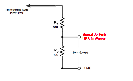
If the mmPi is powered by a 12vDC UPS power supply the software has the capability to monitor the presence of the 12v DC supply and initiate a shutdown after a period of time following a mains power fail, this time period can be set in the software (upsexpired). Following re-connection of the dc supply the mmPi will initiate a restart of the Raspberry Pi .
A small modification of the incoming 12v DC is required by connecting a resistor voltage divider to the DC input. Th output of this divider is connected to J5-Pin 5 (signal ups-nopower) an active low( zero volts) signal will be detected by the mmPi as a power fail condition. Following resumption of the dc supply an active high (>2.4v dc) will be detected and initiate the restart.
A suitable 12v UPS power supply is available from Jaycar Electronics (cat MP5240) but others are also suitable on Ebay, try search 12v UPS for router .
.png)
Instructions
-
All the files required for PCB fabrication by a pcb manufacturer are in the files section below. The board layout is also suitable for isolation milling, the pcb shown in the working prototype for this project was made by cnc milling.
-
Although it would be preferable to use the mmPi pcb designed for the project it would also be perfectly possible to use some other pcb designed to run MMBasic , several PCBs suitable for running MMBasic programs are mentioned on Geoffs web site also in the Components section.
-
In order for mmPi to control the shutdown of the DC power supply a small modification is required, see details below.
-
Information on programming the micro-controller.
-
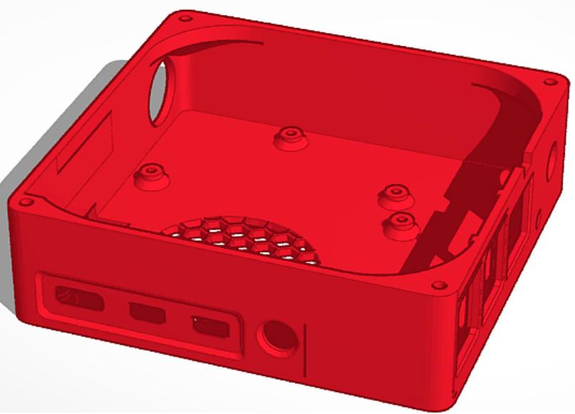
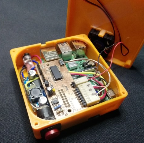
An enclosure has been designed for a mmPi and Raspberry Pi4 combination as shown on this web page. It is 3D printed and the STL files are available in the files section. As mentioned previously mmPi will also run with any of the Raspberry Pi (Zero - Pi4) models.
Setting up the Raspberry Pi
It is assumed that the Raspberry Pi is already setup and working correctly either in Desktop or Headless configuration. In order for the RPI to work correctly with the mmPi pcb a couple lines must be added to the /boot/config.txt file on the Raspberry Pi SD card.
Open /boot/config.txt in nano (or your preferred editor):
sudo nano /boot/config.txt
#This sets up the ability for a pushbutton switch to shut it down:
#Also the Raspberry Pi's status is signaled via Gpio Pin4
dtoverlay=gpio-shutdown,gpio_pin=17
dtoverlay=gpio-poweroff,gpiopin=4,active_low=1
Save and exit the file with control-X, Y <return>.
To have your enclosure fan controlled by mmPi and the Raspberry's cpu temp you will need to create the following script on the Pi.
Create the file,
cat > temp
edit the file just created,
sudo nano temp
enter the following lines in the file,
nb. this assumes the Pi Uart0 is set at 9600 baud (default) , for a useful link on the RPI serial port try here.
#!/bin/bash
temp=`cat /sys/class/thermal/thermal_zone0/temp`
echo "{pi-temp:$(($temp/1000))}" > /dev/ttyAMA0
echo "{pi-temp:$(($temp/1000))}"
crontab -e
Append the following entry
* * * * * temp
Save and close the file.
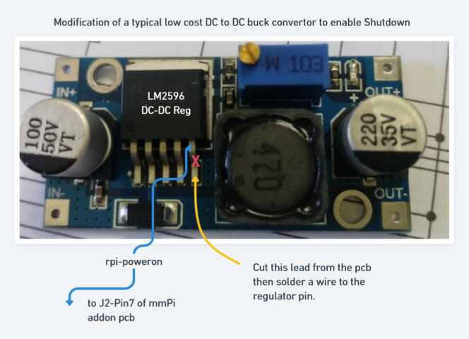
Modifications to DC to DC regulator module (based on LM2596 IC regulator)
This image shows how to modify a typical low cost DC Buck regulator module for use with the project
Programing the mmPi Microchip PIC32MX170 mcu.
Components
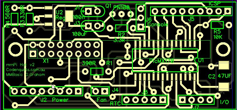
- mmPi v2 pcb, gerber files to contruct the PCB in files section.o
- 1 x Microchip PIC32MX170F256B-I/SO-ND DigiKey
- 1 x PN100
-
1 x Z6334 • DC-DC Buck Module 3-40V In / 1.5-35V Out Altronics
-
1 x 47uF Tantalum Chip Cap, SMD
-
1 x 100uF Electrolytic
-
1 x 0.1 uF cap bypass
-
1 x Resistor 1/4w 330R,390R,560R,3.3K,10K
-
1 x 8 Pin 0.1 90-degree Locking Header - 2.54 pitch - Single HM3428 Jaycar
-
1 x 2 Pin 0.1 90-degree Locking Header - 2.54 pitch - Single HM3422 Jaycar
-
1 x 2 Pin 0.1 Header with Crimp Pins - 2.54 pitch HM3402 Jaycar
-
1 x 8 Pin 0.1 Header with Crimp Pins - 2.54 pitch HM3408 Jaycar
-
1 x 0.100" (2.54 mm) Female Header: 2x8-Pin, Straight POLOLU-1028 Core Electronics
-
1 x 40pin Headers - Straight FIT0084 Core Electronics
-
1 x 5VDC 30mm Thin 2 Wire Fan YX2500 Jaycar
|
mmPi source bas file (umpi-v2-1.36-mm - soic.bas) in zip file |
 |
|---|
|
mmPi v2 PCB Gerbers in , all files in Zip |
|
|---|
|
mmPi 3D printed enclosure files ( STL files) available from thingiverse |
|
|---|
|
mmPi schematic |
 |
|---|
Discussion
Leave Comment